FROM CONCEPT BLUEPRINT TO BENCH VALIDATION.
REVEROB Research & Development operates on a disciplined 7-stage closed-loop engineering lifecycle—progressing from manual drafting blueprints and 3D parametric CAD to additive manufacturing, embedded software integration, and live bench validation.
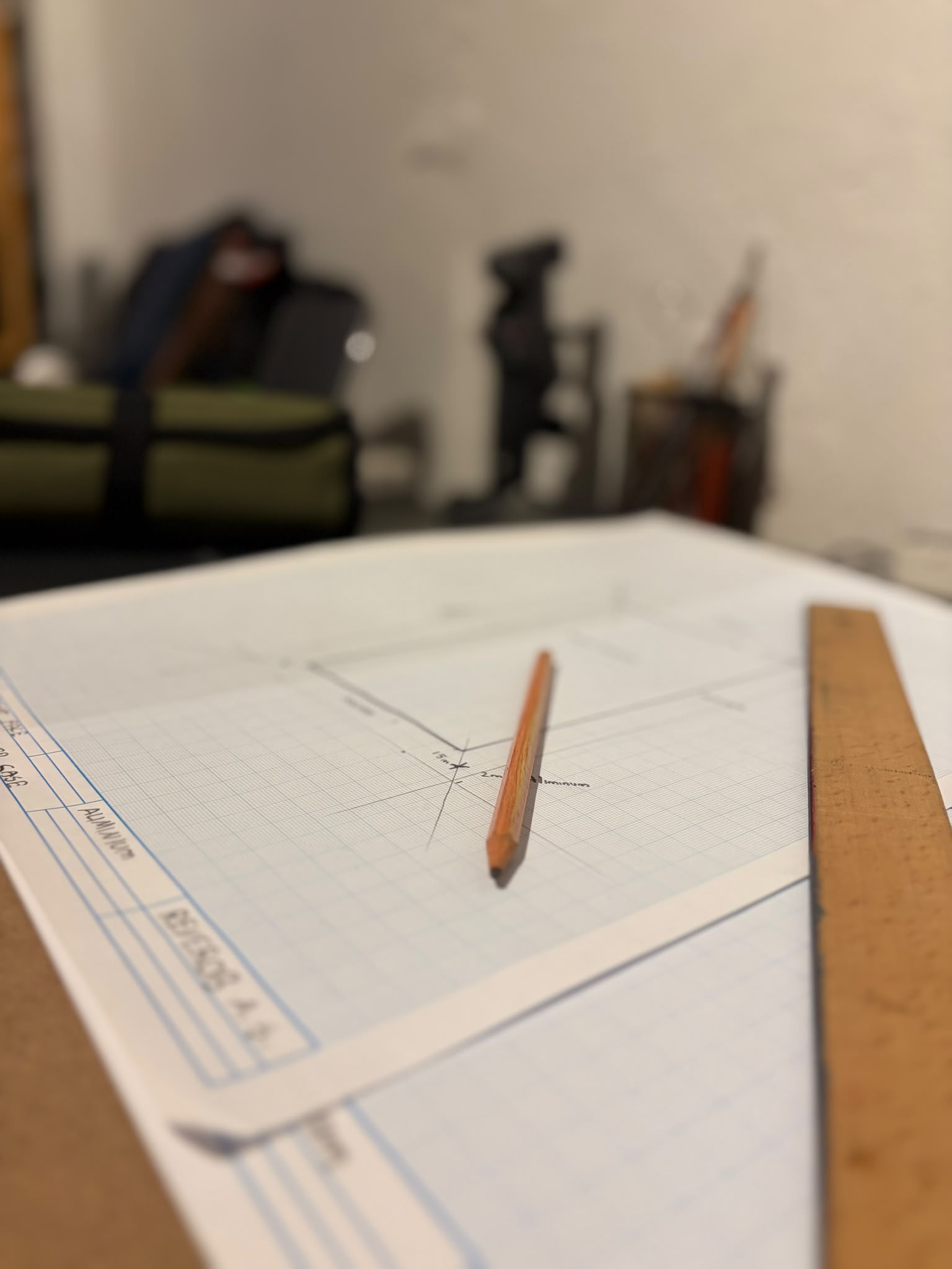
Concept Design & Manual Drafting
Millimeter-Scale Manual Blueprints, Geometric Constraints & Operational Requirements
Every REVEROB project begins on drafting paper before entering digital CAD. Mechanical proportions, center-of-gravity estimates, sensor field-of-view (FoV) cones, and kinematic envelopes are established through manual technical blueprints.
STAGE DELIVERABLES & VERIFICATION CRITERIA
- Scaled orthographic manual drafting blueprints (Top, Front, Side views)
- Mission profile definition and environmental operating envelopes
- Initial dimensional tolerance and internal chassis volume allocation
System Architecture & Subsystem Planning
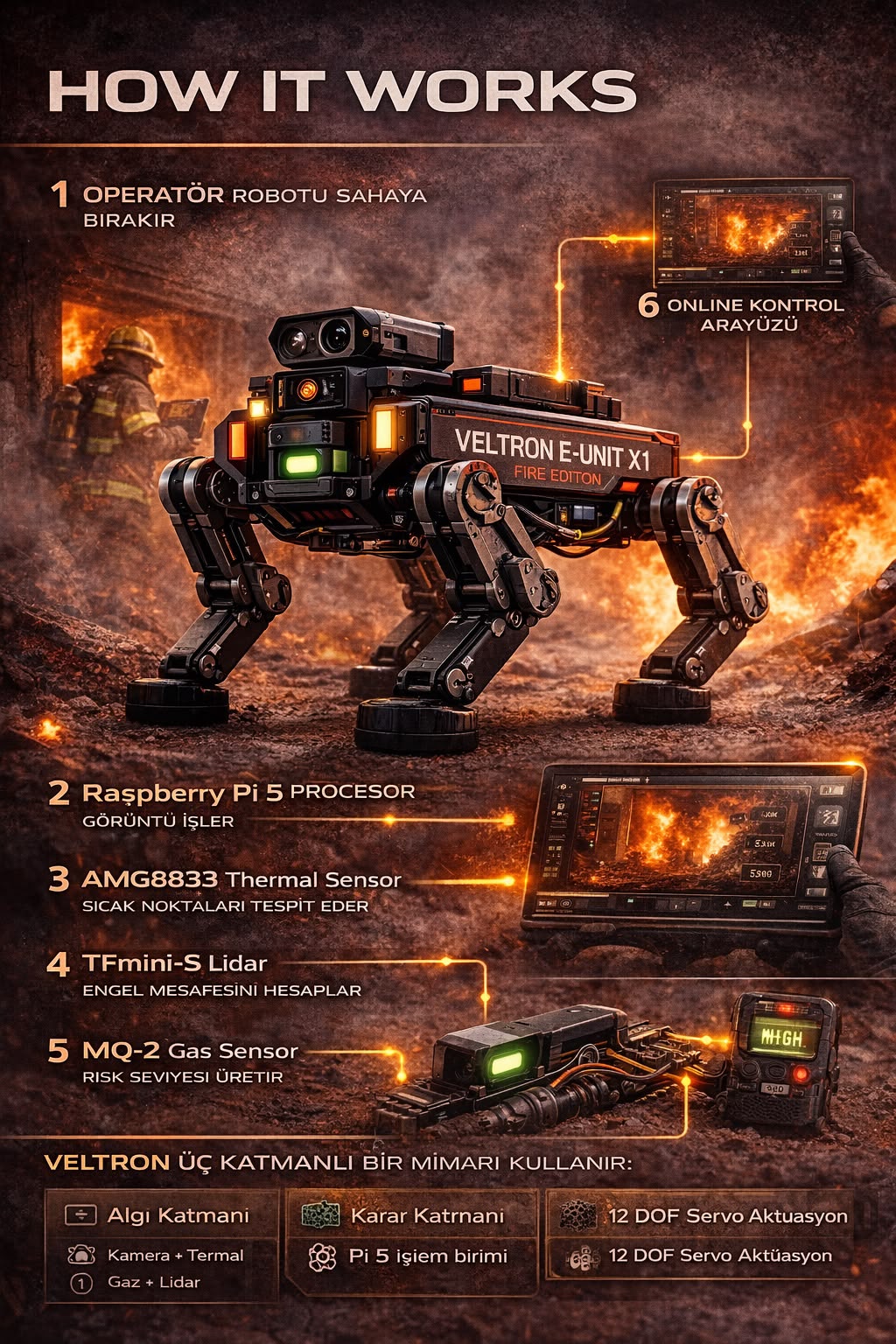
Sensor Topology, Power Distribution, Data Buses & Procurement/BOM Matrix
Once the concept is locked, all robotic subsystems—compute nodes, optical cameras, thermal arrays, LiDAR, gas sensors, motor drivers, and communication links—are mapped into architectural block diagrams and structured BOM procurement trackers.
STAGE DELIVERABLES & VERIFICATION CRITERIA
- VELTRON-E / UNIT X1 subsystem functional topology ("How It Works" architecture)
- Hardware component procurement, BOM, and integration tracking matrix
- I2C, UART, SPI, MIPI CSI-2, and PWM bus/pinout allocation

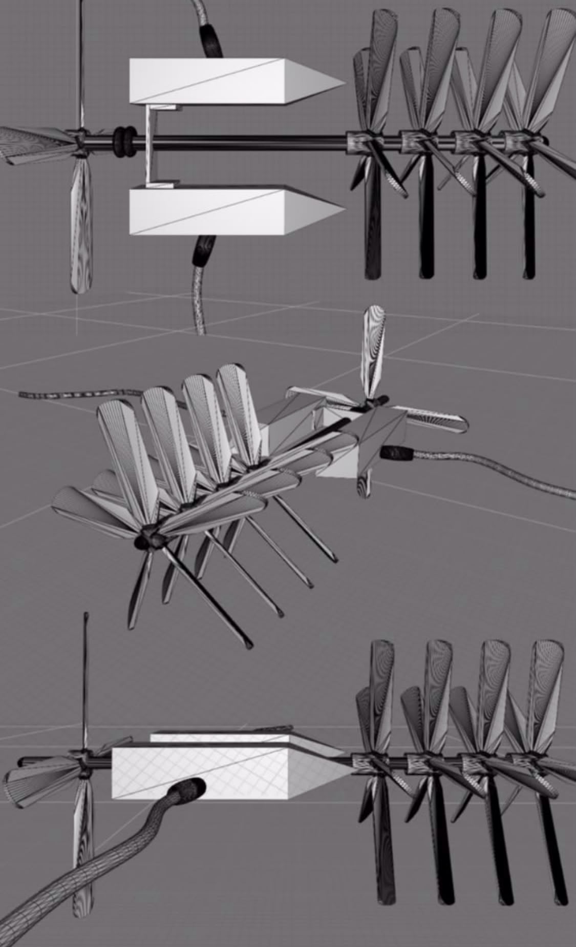
Hardware Development & 3D CAD Modeling
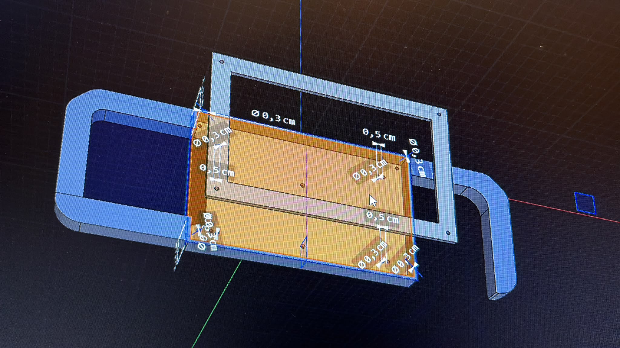
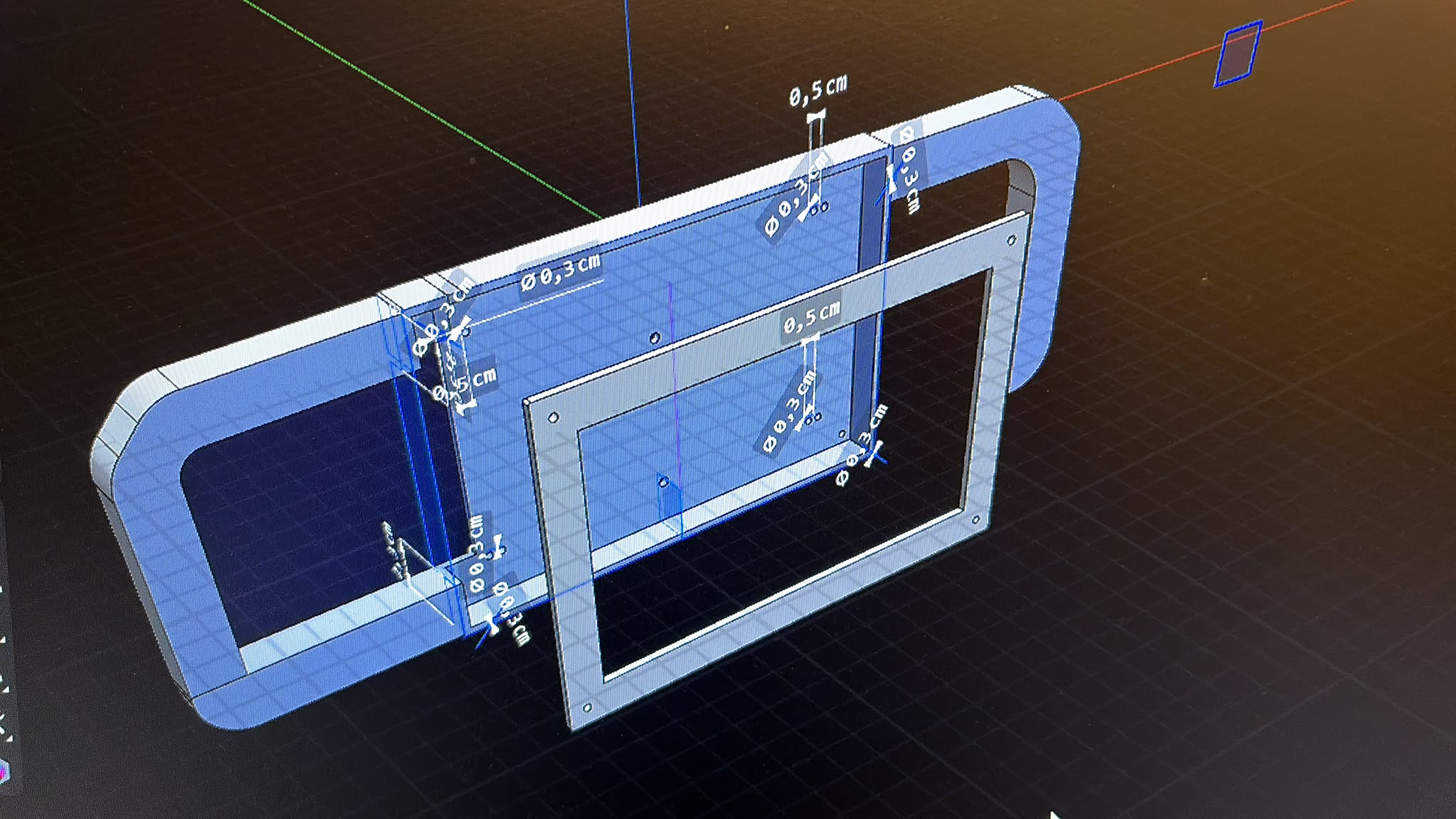
Parametric Solid Modeling, Ergonomic Controller Enclosures & Turbine Rotor Geometry
3D parametric CAD assemblies are engineered with millimeter-accurate mounting bosses for PCBs, sensors, and actuators. From custom handheld controller enclosures to high-RPM axial turbine rotor blades, every geometry is digitally verified.
STAGE DELIVERABLES & VERIFICATION CRITERIA
- Custom field handheld controller upper/lower shell parametric CAD modeling
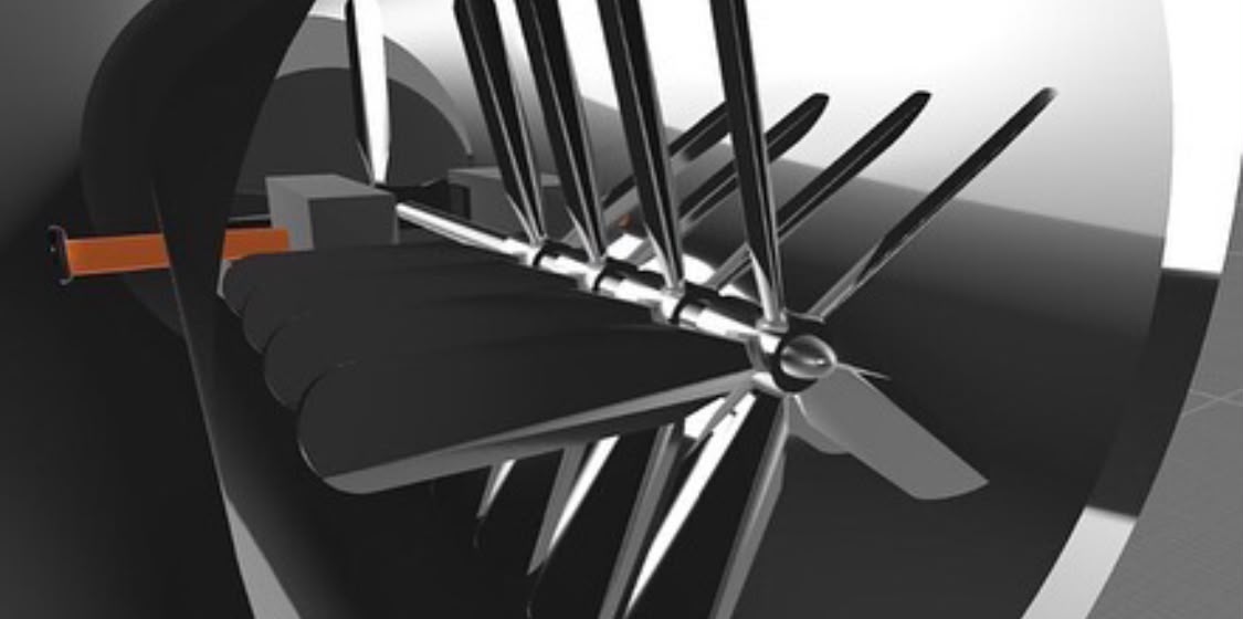
- Axial micro-turbine rotor and compressor blade wireframe geometry analysis
- Design for Additive Manufacturing (DfAM) and print orientation optimization
Software Integration & Command Interfaces
REVEROB OS, Embedded Firmware, YOLOv8 Vision Pipeline & Field Operations App
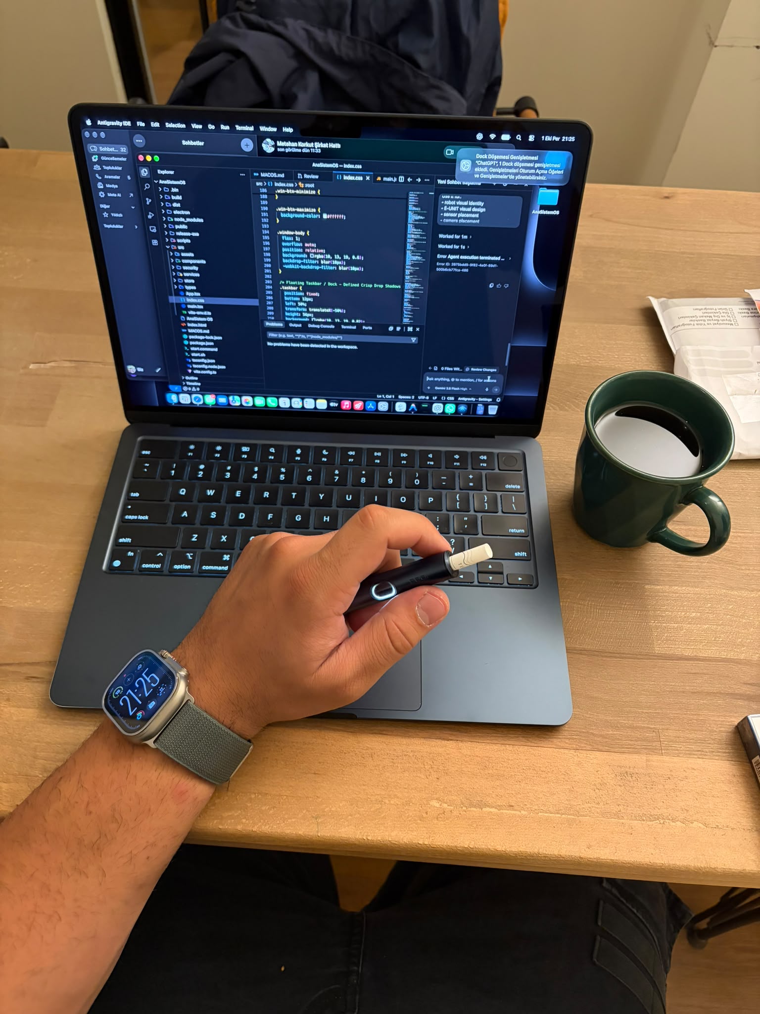
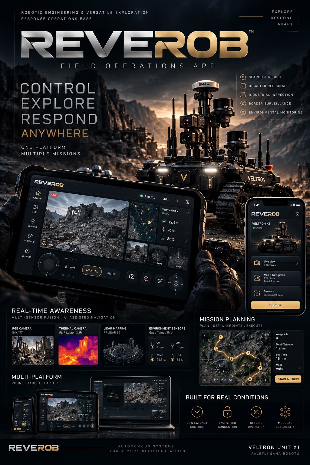
Hardware subsystems are unified with the REVEROB OS software stack. Embedded device drivers, real-time camera/telemetry streams, and desktop/mobile field operation interfaces are coded and integrated.
STAGE DELIVERABLES & VERIFICATION CRITERIA
- REVEROB OS desktop (React + Electron) and mobile field command interfaces
- YOLOv8 + Kalman Filter computer vision and HUD telemetry integration
- 2FA operator security and OTA Update Center deployment infrastructure
Prototype Assembly & Electromechanical Build
3D-Printed Enclosure Build, Optical Camera Assembly & Turbine Shaft Integration
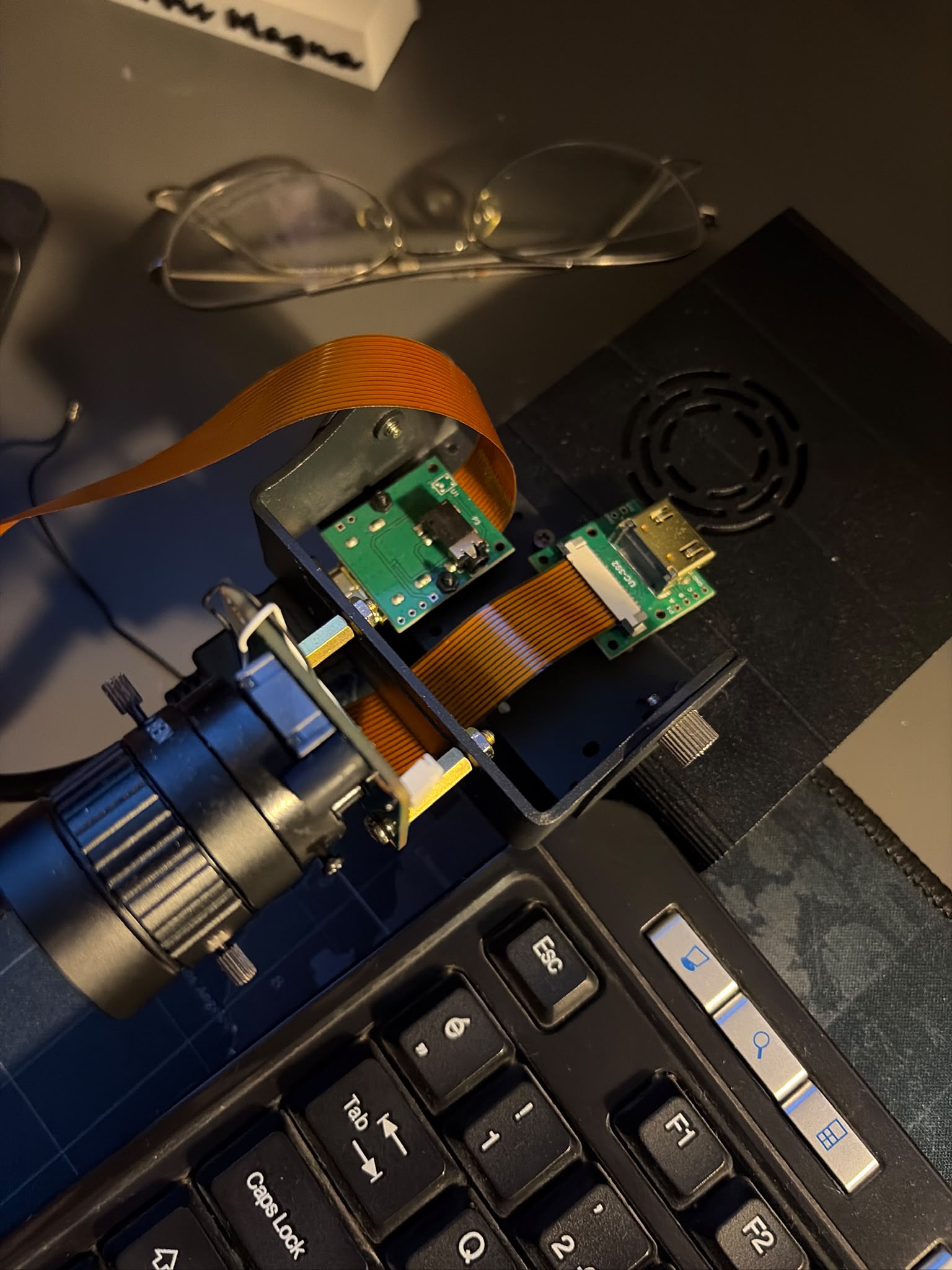
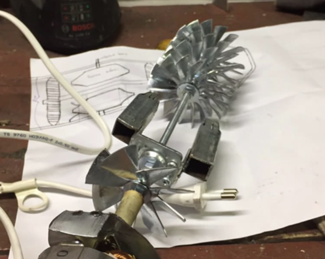
Fabricated mechanical components, PCBs, optical sensors, and bearing/shaft assemblies are physically built on the engineering bench. Wiring harnesses, solder joints, and mechanical clearances are verified.
STAGE DELIVERABLES & VERIFICATION CRITERIA
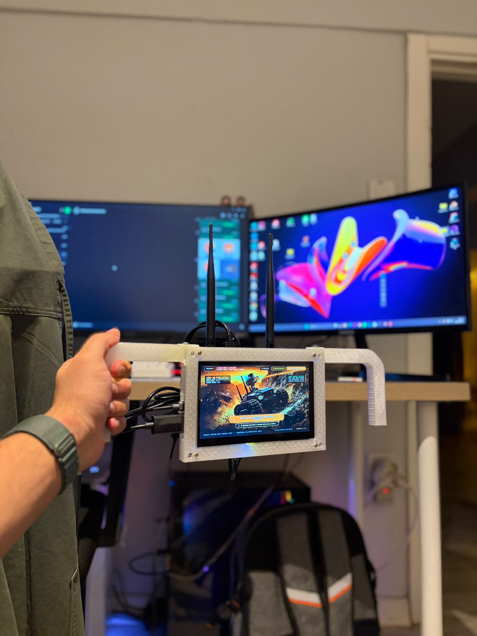
- Physical VELTRON handheld controller assembly and analog joystick calibration
- UC-392 / IMX477 CSI camera and industrial C-mount lens mechanical assembly
- Precision assembly of the micro-turbojet compressor, turbine, and main shaft
Testing, Live Ignition & Bench Validation
Live Micro-Jet Ignition Testing, Embedded Video Streaming & Sensor Calibration
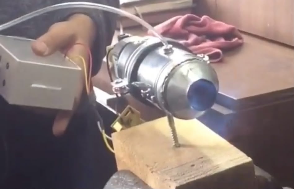
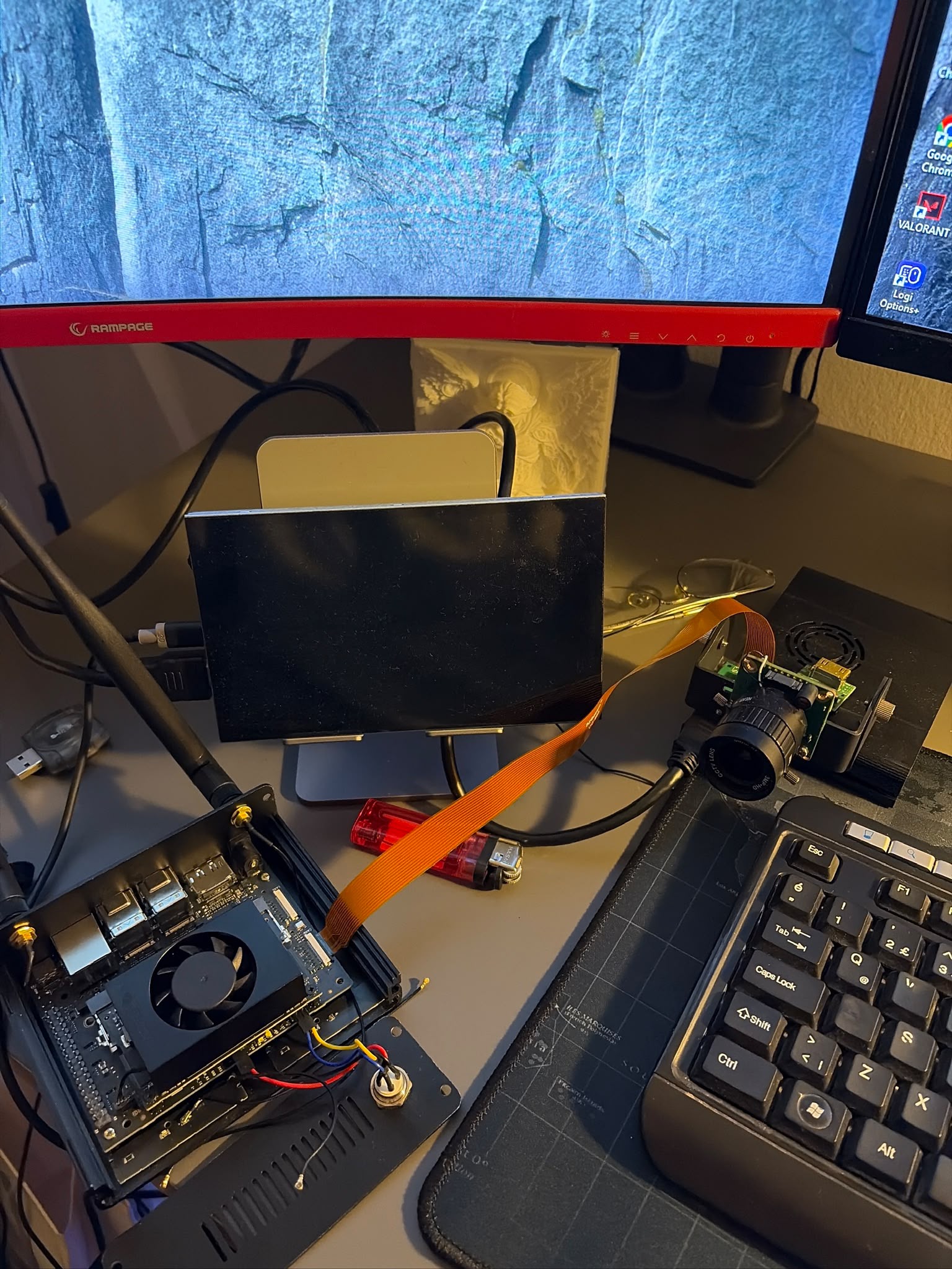
Every assembled subsystem undergoes rigorous functional validation under real operating loads. The micro-jet engine is tested under live fuel ignition, while embedded camera and display pipelines are verified for latency and thermal stability.
STAGE DELIVERABLES & VERIFICATION CRITERIA
- Live flame ignition and combustion validation of the stainless-steel micro-jet engine
- End-to-end video latency verification across the SBC + CSI camera + 7" IPS bench
- Threshold calibration of ultrasonic, LiDAR, thermal, and gas sensor arrays
Iterative Improvement & Architectural Evolution
Telemetry-Driven Redesign, Thermal/Flow Optimization & Next-Gen Platforms
Thermal, structural, and software findings gathered during bench testing feed directly back into CAD models and firmware repositories. This continuous loop refines both the VELTRON UNIT X1 platform and internal turbine architectures across revisions.
STAGE DELIVERABLES & VERIFICATION CRITERIA
- Revision of VELTRON UNIT X1 chassis armor and sensor mast ergonomics
- Refinement of micro-jet internal flow channels and cutaway rotor geometry
- OTA software updates pushed to field robot nodes via REVEROB Update Center
Case Study: Integrating Mechanical CAD, Bambu Lab / Creality Slicers, Embedded Computing & AI
REVEROB operates an in-house design-to-fabrication workflow capable of translating digital CAD revisions into functional robotic hardware, embedded assemblies, and AI-enabled systems within hours.
Parametric Tolerance Design
Sensor bays (IMX477, AMG8833, TFmini-S), screw standoffs, and cable routing channels are modeled in 3D CAD with thermal shrinkage allowances.
Bambu Studio & Creality Fabrication
Parts are sliced in Bambu Studio and Creality toolchains with optimized layer orientation, structural infill patterns, and tree supports before high-speed FDM fabrication.
SBC, MCU & Sensor Embedding
Raspberry Pi 5, ESP32, NRF24 RF modules, 7-inch IPS driver PCBs, and analog joysticks are mounted directly into the printed enclosures.
YOLOv8 & Command Link
Once powered on, live video streaming, YOLOv8 object detection, and bidirectional telemetry control are activated through REVEROB OS.
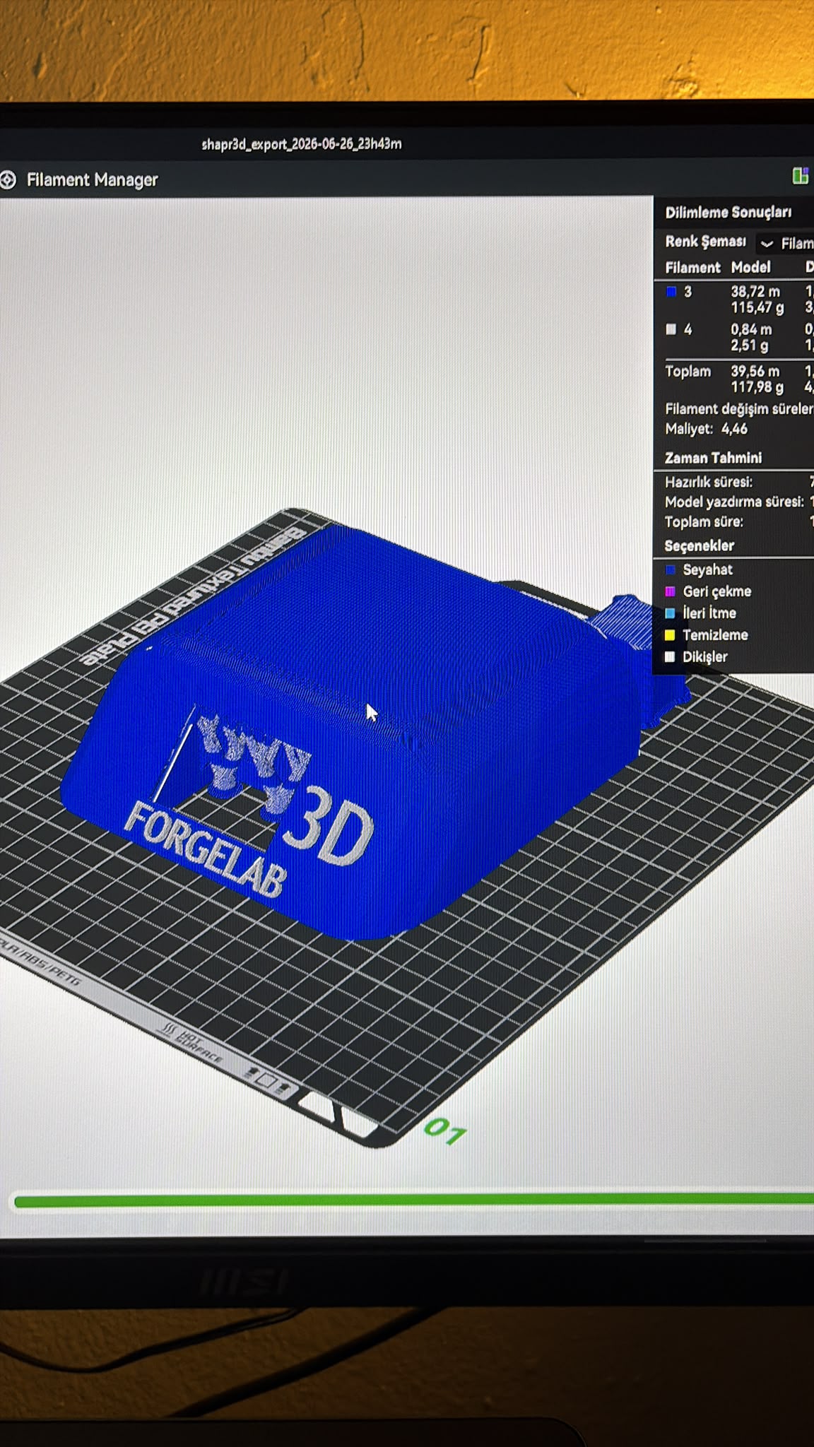
Bambu Studio Slicer Toolpath & Layer Geometry Preview
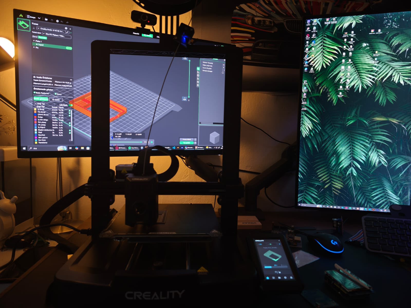
Functional Prototype Fabrication on Creality Ender-3 V3 KE
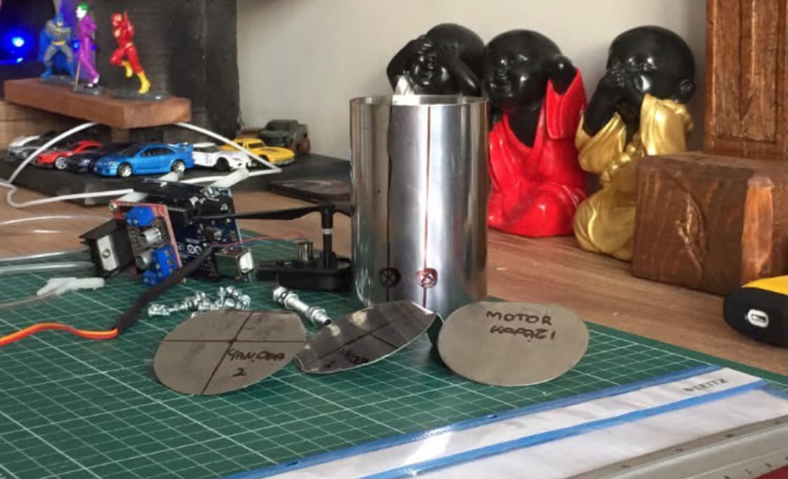
Stainless-Steel Micro-Turbine Casing & Arduino Control Bench